Reverse Engineering a 12V Fluorescent Driver: From BJT to MOSFET
Overview
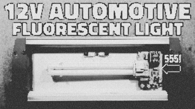
Reverse engineering old hardware reveals the clever, if sometimes baffling, hacks of previous eras. This tutorial breaks down a 12V automotive fluorescent light driver. We analyze how a 555 timer chip manages high-frequency oscillation to strike a tube and how to perform a successful component transplant when original parts like the D44 H11 transistor go obsolete.
Prerequisites
- Understanding of DC voltage (12V) and polarity.
- Basic soldering and PCB cleaning techniques.
- Familiarity with reading electronic schematics.
- Knowledge of transistor types (BJT vs. MOSFET).
Key Libraries & Tools
- Acetone & Cotton Buds: For removing protective PCB paint to identify component markings.
- Multimeter: Essential for checking capacitor values and transistor continuity.
- Schematic Capture: To map out traces and understand the 555 timer chip logic.
Circuit Walkthrough
The heart of the board is the 555 timer chip. It generates a fixed frequency to drive the primary side of a step-up transformer.
// Logic representation of the 555 output driving the transistor
void drive_inverter() {
    while(power_on) {
        set_pin(3, HIGH); // Pulse to transistor base/gate
        delay_us(frequency_constant);
        set_pin(3, LOW);
        delay_us(frequency_constant);
    }
}
A critical pre-heat stage occurs via a PTC thermistor. At startup, current flows through the heaters; as the thermistor warms and its resistance climbs, voltage is forced across the tube to strike the arc.
Syntax Notes
- Zener Configuration: The use of 7.5V and 2.4V Zener diodes in series on Pin 5 is a hardware "syntax" for voltage stability, likely countering vehicle alternator fluctuations.
- Transistor Logic: While the original used an NPN BJT, a logic-level STP36NF06L MOSFET serves as a drop-in replacement with higher efficiency.
Tips & Gotchas
- Capacitor Fatigue: A 100nF capacitor that drops to 40nF will cause heat issues and eventual failure. Always check for bulging or "doming."
- Polarity Protection: This circuit uses a shunt diode. If you reverse the 12V leads, the diode shorts the supply to blow the fuse rather than frying the timer chip.
- 555 timer chip
- 43%· products
- D44 H11
- 14%· products
- PTC thermistor
- 14%· products
- STP36NF06L MOSFET
- 14%· products
- Zener diodes
- 14%· products
Retro 12V fluorescent light driver with pre-heat
Watchbigclivedotcom // 7:51

The trashiest electronic channel on YouTube. We test and use affordable electronic soldering equipment and tools to build, teardown, modify (and sometimes destroy) random electronic stuff. A British TV licence is NOT required to view my videos or almost every other video on YouTube. Many of the builds and projects featured here operate at full mains voltage and carry a high risk of shock and fire. As such they're really intended for either entertainment value or for those who do similar stuff. The videos are generally uncensored and may contain tasteless jokes, profanities and even blood and electric shocks when things go wrong. So just like a normal workshop really. So kick back, grab a beer and enjoy the ride.